Cables and Lines for Hazardous Areas
Significance of the decision which cables and cable glands can be used for ex-applications / Responsibility of the installer and operator
Properties of cables and lines in explosive areas are an integral part of the electrical explosion protection. Thats why the selection of suitable cables and cable entry components, as well as the combination of them is so important. At a first glance, it seems to be simple and trivial but actually this is not the case. The classic European explosion protection (Directive 2014/34/EU, hereinafter, ATEX Directive") refers to a device, for example, a lamp, a measuring instrument, a camera, or the like. Safety of such devices is usually ensured by the use of one or several ignition protection types which are clearly defined in the applicable norms and standards: For example, IEC/EN 60079-1 standard describes the function of the ignition protection type "Flameproof Enclosure". The responsible party for complying with this ignition protection type is the manufacturer of the device. In general, to get an approval of an ex-protected device, the manufacturer can proceed, as follows:
- He determines the design of the device and the applicable protection type in order to make the device safe.
- Then a testing laboratory, selected by the device manufacturer (for example, PTB in Brunswick, Germany), checks whether the design of the manufactured device complies with the safety requirements.
- If the device passes all tests, the testing laboratory issues a certificate of conformity and the manufacturer can introduce the device to the market.
But: Neither the manufacturer nor the testing laboratory are obliged to determine in detail, what kind of cable gland has to be used. Moreover, for the above-mentioned certification of flameproof devices (Ex-d) or devices with increased safety (Ex-e), there are no defined requirements on cables and cable glands which have to be used and neither the cable itself nor the cable glands are determined, much less tested. Cables and lines are not included in the scope of the ATEX Directive and therefore cannot be certified in accordance with it. If an improper cable or cable gland is selected, the entire protection system can become unsafe. This can cause problems as the following example shows: A flameproof device (Ex-d) generates 10 bar of explosion pressure; however, the selected combination of cable and cable gland can withstand only 6 bar. As a result, the device is not safe.
Summary:
- Usually the manufacturer tests the flameproof devices without cables.
- Cables and lines are not included in the scope of the ATEX Directive.
- Improper cables and/or cable glands can impair the device’s protection class and cause an explosion.
The international standards (IEC) as well as the European norms (CENELEC) are aware of this problem: The norms and standards of the applicable ignition protection categories (Ex-d, Ex-e), determine more and more concrete and in detail the general as well as specific requirements of cables and wires. This also applies to the “user norm": IEC/EN 60079-14: Electrical installations design, selection and erection. The technical scope, e.g. for cable glands, is defined in the standard IEC/EN 60079-0/1 for devices, however, it is not the device manufacturer’s obligation to select the proper cables and lines. This is an obligation of the installer and/or operator of plants in the hazardous area. This transfer of responsibility is difficult but sensible and basically, the responsibility hierarchy defines the following procedure:
- The device manufacturer is responsible for his device, namely up to the thread into which the cable gland is introduced.
- The manufacturer of the cable gland is responsible that the cable glands for defined cable types (e.g. of certain diameters, from/to) are safe up to a pressure of 30 bar.
- Finally, the installer and/or operator of the Ex-device are responsible for the correct selection of the suitable cable and matching it with the appropriate cable gland.
General requirements for cables and lines / Mechanical design
General requirements for cables are described in Section 9.3 of the IEC/EN 60079-14 norm. Commonly used for configuration and planning tasks are regular copper or fibre-optic cables. Of course, a cable for hazardous areas should be mechanically robust. No engineer would come up with the idea of taking a regular office network patch cable and install it in an hazardous area. But when is a cable considered to be mechanically robust? The IEC/EN 60079-14 norm determines the following:
Jacket material
The outer sheath of the cable must be made of thermoplastic, thermosetting, or elastomeric material.…
Almost all commercial cables fall into one of these categories. For example, PUR cables can be duroplastic, thermoplastic or elastomeric, depending on the degree of cross-linking.
Shape of the Cable
Cables must be circular and compact … They must be circular, because the cable entries have circular rubber seals, which assure the necessary sealing of the cable. They must be compact, because a less-compact stranded line will not withstand the contact pressure of the cable gland’s rubber ring. In this case, the static friction between the rubber ring and cable will not be sufficient to ensure the necessary compressive strength. Especially when introducing the cable directly into the flameproof enclosure (Ex-d), the cable’s circular shape and compactness are major technical properties ensuring the cable safety.
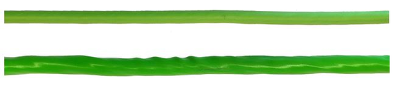
However, this standard does not explicitly define any permissible tolerances regarding the cable’s circularity shape and it does not explicitly determine the maximum permissible deviation from circularity so that the cable is still considered "circularly stranded”. In order to verify the cable’s suitability, we use a simple overpressure test for our Ex-Cables: The combination of an Ex-d enclosure, a cable and a cable gland must withstand a pressure of 30-bar without the cable getting loose from the cable gland. Terminal compartments or boxes with increased safety (Ex-e) do not need to withstand high pressures. In this case, the requirements on cable compactness and circularity are derived from the protection category and the design of the respective Ex-e cable entry.
Embedding and fillers
Any bedding or sheath shall be extruded. Fillers, if existing, must not be hygroscopic … Today, pressure or sheath extrusions are standard technologies used in cable production and modern commercial cables are provided with non-hygroscopic fillers. If in doubt regarding these two parameters, ask the manufacturer of the cable.
Potential ignition/flame transmission
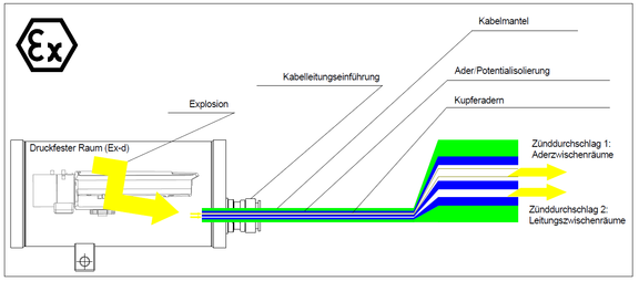
Theoretically, especially in large flameproof housings with correspondingly high explosion pressures, flame transmission through the cable can occur. This issue is, only rather generally, described in Section 9.3.2 of IEC/EN 60079-14. Basically, the requirement is: Any potential probability of flame transmission through the cable (e.g., gaps between wires) must be prevented. But it is neither explained nor described what kind of cables may allow this phenomenon nor how to prevent such risks.
Potential flame transmission between insulated cores
Copper wires and their insulation are usually circular. Thus, if such components are not pressure-extruded but simply twisted with each other, there will be some clearance or gap between them through which gas and air can escape. If the "shape" (length-to-width ratio) of such clearance is worse than the shape of the housing’s flameproof gap, the cable will be the bottleneck of the Ex-d protection category.
The consequence is that the length and the mechanical robustness of the cable are important parameters. The longer the cable, the greater the length-to-width ratio of a potential gap and thus the safer the system.
Where do you have to anticipate this risk?
This risk exists if the cable does not meet the criteria for the of prevention zone entrainment, i.e. when the wire has poor longitudinal tightness (see appendix E of the IEC/EN 60079-14).
How to face this risk correctly?
For this purpose, the IEC/EN 60079-14 standard offers two possible measures: The first one is to use IEC/EN 60079-14 barrier glands (see Section 10.6.2). In such glands, the clearance between insulated cores is filled with modelling clay or cast resin (compound). Such barrier glands reliably prevent the flame transmission between the insulated cores, however, a disadvantage is the higher labour costs due to the kneading of the compound. Moreover, such cable glands cannot be installed at low temperatures because the compound needs a certain minimum curing temperature. The second possible method is to use a cable which is as long as possible, provided that it is sufficiently robust. In this respect, the IEC/EN 60079-14, Section 10.6.2 requires a minimum length of three meters. This method makes sense: the cable length directly influences the length-to-width ratio of the cable.
Potential flame transmission between individual cores
Individual wires can be stranded (braid). For example, AWG22/7 reflects a braid with 7 circular stranded single core wires, whereas AWG22/1 is a rigid wire. In these cases, too, there are clearances between individual circular cores causing the same problem as described above. Here also, if push comes to shove, there is a bad length-to-width ratio of the clearance between the cores, thus impairing the flame-proof gap of the entire protection system.
Where you have to anticipate this risk?
This risk exists if the wire does not meet the criteria for the prevention of zone entrainment, i.e. the when the wire has poor longitudinal tightness (see appendix E of the IEC/EN 60079-14).
Note: The flame transmission caused by clearances between the wire cores of large cross-sections is higher than of smaller cross-sections - simply because of the shape geometry. We only know a prototype-examination in which flame transmission was proven for a very short wire (Ex-d - Ex-e-wire cable bushing) of 95 mm2 nominal cross section.
How to face this risk correctly?
A barrier gland does not prevent hazards. For maximum permissible cross-sections and cable lengths, refer to the respective user manual. Moreover, you should also pay attention to the mechanical robustness of the cable and to the required minimum length of 3 metres.
Risk of zone entrainment and longitudinal tightness
The "longitudinal tightness" or "pressure resistance in longitudinal direction" or "longitudinal breathing" is a certain property of the cable. It derives from the cable structure and can be precisely measured. Hereinafter, this property is referred to as "longitudinal tightness" of a cable. Regarding the explosion protection, it is an important criterion - in two respects:
- Cables with a good longitudinal tightness are safer with regard to prevention of flame transmission (device safety).
- Long cables of a good longitudinal tightness reliably prevent zone entrainment (safety of devices and plants).
So the above are actually two good reasons to go into greater detail and to explain the terms “longitudinal tightness” and “zone entrainment”.
What does longitudinal tightness mean?
What does the longitudinal tightness actually mean? We easily test it for our Ex-Cables on the basis of our test rig for the cable longitudinal measurement: A pressure-resistant 5-litre box has two ports: The first port is intended for connecting an air pump, the second one is for connecting the cable which is supposed to be tested. What would happen if the you pump up a vessel, e.g. with 300Pa (which is actually not a lot)? The result will range between two extremes: If the cable is in longitudinal direction hermetically tight, e.g. like a steel bolt, the pressure remains at 300Pa since the air cannot escape. However, if the cable leaks like a water hose, the pressure in the vessel will rapidly drop. Conclusion: If you stop the time which is needed for a defined pressure drop (e.g. between 300Pa and 150Pa), you will get a reliable criterion for the longitudinal tightness: For cables with a good longitudinal tightness, the pressure drop from e.g. 300Pa to 150 Pa, takes at least 5 seconds. For cables with a poor longitudinal tightness, the pressure will drop much faster. Please note: Fibre-optic breakout cables hold the pressure less than one second!
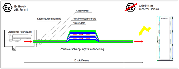
What does zone entrainment mean?
Usually cables are used to connect a device with a control cabinet – if necessary, via a terminal box. Explosion-proof devices are typically placed in ATEX zones 1 or 2 whereas control cabinets are usually installed in safe areas. This means that the cable which connects a device with a control cabinet typically connects two different ex zones: for example, Ex zone 1 and a safe area. So if the cable has a poor longitudinal tightness and, in addition, an unfavourable pressure condition, it can happen that the gas starts to escape through the cable. The explosive gas can penetrate into the safe area and cause an ignition. That is why such explosive gas escaped is also called “zone entrainment”.
How to face this risk correctly?
If possible, cables with a good longitudinal tightness and which fulfill the criteria of IEC/EN 60079-14 should be used. Our Ex-Cables do this. If this is not possible, e.g. in case of fibre-optic cables, you can improve the situation by using threaded barrier cable glands. They will reliably prevent the gas escape though the clearance between the insulated wires. If you have to patch several cables with poor longitudinal tightness in an electric enclosure, you can also consider creating a light atmospheric excess pressure e.g. by means of a suitable air conditioning system. The slight excess pressure (in comparison to the field) in the electric enclosure can prevent the risk of zone entrainment.
Environmental, process and application parameters
Flame resistance
The requirements on flame propagation are described in Section 9.3.9 of the IEC/EN 60079-14 norm. Cables must be flame-retardant in accordance with IEC 60332-1-2 (see our Ex-Cables), or IEC 60332-2-2 which means that if the cable is exposed to a 1KW flame, no flame propagation should occur. Otherwise, an ignitable spark in the safe area would be transmitted via the cable in the ex-area which inevitably would cause an explosion. If flame-retardant cables are not available for these applications, the norm offers options such as fire-safe laying of cables or fire barriers for such cases. In the practice, firewalls are often used, however, if possible, it is better to use flame-retardant cables.
UV Resistance
If the cables in explosive areas are exposed to ultraviolet (UV) rays, the cable’s UV resistance is a very important characteristic. If a cable is not UV-resistant, it will lose its steadiness when exposed to UV rays and become porous. Consequently, an important requirement such as robustness of the sheath is no longer guaranteed. Only in Section 9.3.7, the IEC/EN 60079-14 standard describes risks and dangers of UV rays, stating that cables are laid in such a manner that they are protected against the effects of UV rays, though in practice this is not always possible.
How to face this risk correctly?
If there is a risk of UV exposure, always use UV-resistant cables. Our Ex- Cables are sunlight resistant in accordance to UL 2556 Sec. 4.2.8.5 (720h).
Surface Temperature
Depending on the electric current loads, wires and cables can get hot. In the hazardous area, hot surfaces can cause an ignition (the ignition temperature of carbon disulphide lies at only 95°C). Thus, it is clear that the cable must not become hotter than the equipment to which the cable supplies the electric current. Or, to put it another way: the surface temperature of cables must not exceed the temperature class of the system. The IEC EN 60079-14 standard deals with these issues in Section 9.3.8.
Ambient Temperature
This characteristic is not defined in the installation standard, probably, because it is self-explanatory: Use the cable only within the ambient temperature range specified by the manufacturer.
Oil and Mud Resistance
Especially in the off-shore sector, hazardous areas are often polluted with oil or drilling mud, e.g. in "shaker-rooms" or on drilling platforms. In such cases, you should make sure that the cables withstand these rough ambient conditions. The basic rule is: oil and drilling sludge pollution must not impair the cable’s properties which are relevant for the explosion protection. The IEC/EN 60079-14 building and installation does not deal with this subject but you can refer to the IEC 60811-2-1 standards (e.g. IRM 902, 4h at 70°C) for oil resistance, as well as to the Norwegian standard NEK 606 for drilling sludge resistance. These relevant tests were made for our Ex-Cables.
Installation
Since the European standards and the IEC explosion protection norms apply to the devices and not to the cables, the latter must be laid so that they are protected against damage. The IEC/EN standard deals with the installation issues in Chapter 9.3.7 "Avoidance of damage". The main rules are:
- When laying the cables, protect them in such a way that they withstand all possible mechanical, chemical and environmental risks.
- Pay attention to the maximum permitted bending radi (min. 8 x Da).
- Do not bend the cable directly behind the gland. Leave a few centimetres (min. 2.5 cm) of a straight cable behind the gland.
Flexible Cables for Stationary or Mobile Devices
In hazardous areas, generally also flexible cables can be used for stationary devices as many times, drag-chain cables are required for applications. Nevertheless, it is sensible to examine closely the application. How many cycles has the cable to withstand? At what bending radius and temperature? Best is to discuss the application requirements with the cable manufacturer. The relevant standard is very vague: everything can be planned and used - from a robust plastic insulated cable up to a light rubber hose cable - as long as it is ensured that the cable cannot be damaged. If you have to plan cabling for portable and mobile devices, you should also look up the sections of the IEC/EN 60079-14 Building and Installation Standard regarding the maximum voltages, currents, cross-sections, as well as the grounding requirements (see SKD04-T.flex).
Fibre-optic Cables
In hazardous areas, fibre-optic cables, especially directly inserted into flameproof chambers, are considered potentially more critical than copper wires. In this case, it is not relevant how much energy is transported, but rather what longitudinal tightness can be achieved by the cable. In practice, neither classic fibre-optic cables with or without cable dividers nor "breakout cables” are known which comply the criteria for longitudinal tightness in accordance with Annex E of IEC/EN 60079-14. Classic fibre-optic cables with cable dividers or splice fields require a lot of space. For such an installation, it is advisable to use an Ex-e terminal chamber. This reliably prevents flame transmission through the cable; however, it does not exclude the risk of zone entrainment. Breakout cables can be quite easily inserted into Ex-d chambers. They are already pre-fabricated for plug-in assembly.
For fibre-optic cables, the following rules stood the test of the practice:
- For cable glands into flameproof chambers, always use barrier glands to reduce to a minimum the risk of flame transmission through the cables.
- Ensure mechanical robustness and circularity of the cables.
- If in doubt, ask the manufacturer of the cable glands whether they are compatible with the fibre-optic cable selected by you.
Selection of the Cable Gland
The selection of suitable cable glands is described in detail in Section 10 of IEC/EN 60079-14. Among the criteria described above, the following rules can be derived from the cabling practice for direct Ex-d entries:
- Always use device-certified glands which comply with your device, both in terms of the explosion protection parameters, and with regard to the ambient parameters.
- If all the parameters are fulfilled and the cable is at least 3 metres long, cable glands with rubber ring sealings can be used.
- If the cable is shorter than three meters, use barrier glands.
- If there is a risk of zone entrainment and the cable has no sufficient longitudinal tightness, secondary measures must be initiated in order to prevent zone entrainment.
Note: These rules and recommendations for the practice do not relieve the reader from the necessity to carefully read and understand the IEC/EN 60079-14. SAMCON bears no liability for the above recommendations.
Sources:
Directive 2014/34/EG:
IEC/EN 60079-0
IEC/EN 60079-1
IEC/EN 60079-7
IEC/EN 60079-14
UL 2556 Sec. 4.2.8.5 (720h)
NEK 606
IEC/EN 60811-2-1