User Manual ExCam IPM1137-LE
Safety instructions
Attention
- Absolutely observe the installation's safety directions of the T08 ExCam series and the installation's safety directions of the T20 liteServer series!
- Observe the instructions stated on the type plate!
- The camera is not suitable for use in zone 0 and 20!
- Temperature class and explosion group must be absolutely adhered to!
- The specified temperatures have to be observed!
- The customer is not allowed to make any alterations of the camera.
- The camera must be operated in a proper and sound condition and only in the way intended.
- Repairs may only be carried out by using original parts from the manufacturer. Repairs which affect explosion protection may only be carried out in accordance with the nationally applied regulations and exclusively by the manufacturer.
- When installing the ExCam adhere to the requirements of the EN/IEC 60079-14.
Warnings
WARNING:
DO NOT OPEN IN POTENTIALLY EXPLOSIVE ATMOSPHERES
Observe the safety instructions in the installation guide!
--------------------------------------------------------------------------------------------------------
ВНИМАНИЕ:
НЕ ОТКРЫВАТЬ в потенциально взрывоопасных средах
Соблюдайте инструкции по технике безопасности в руководстве по установке!
---------------------------------------------------------------------------------------------------------
AVERTISSEMENT:
NE PAS OUVRIR EN ATMOSPHÈRES EXPLOSIBLES
Respectez les consignes de sécurité dans le guide d'installation!
---------------------------------------------------------------------------------------------------------
AVISO:
NÃO ABRIR DENTRO DE UMA ÁREA COM PERIGO DE EXPLOSÃO
Observar as instruções de segurança nas instruções de instalação!
---------------------------------------------------------------------------------------------------------
Attention!
The sight glass must not be directly covered by foreign objects. The light must be able to leave the optics of the protective housing unhindered. Regular cleaning intervals of the sight glass should be observed in order to avoid adhesion and dust deposits.
Risk of burns from hot surfaces (≤80°C)!
Do not stare into the direct beam. Danger of impairment of vision due to high exposure to light!
Technical data
Explosion protection
| Identification marks acc. to Directive 2014/34/EU |
Ex II 2G (zone 1 and 2) |
| Ex II 2D (zone 21 and 22) | |
| Explosion protection ExCam | |
| Explosion protection (gas) | Ex db IIC T6 Gb |
| Explosion protection (dust) | Ex tb IIIC T80°C Db |
| Explosion protection (gas) | Ex db IIC T5 Gb |
| Explosion protection (dust) | Ex tb IIIC T95°C Db |
| Protection level ExCam | IP68 (IEC /EN 60529) |
| Protection level liteServer | IP 66/68 (IEC /EN 60529) |
| Transport/ storage temperature | -40°C…+65°C (non-condensing) |
| Ambient temperature (EX) | -30°C…+50°C |
| Named testing laboratory | TÜV Rheinland (number 0035) |
| Camera | |
| EU type approval certificate | TÜV 18 ATEX 8218X (2018) |
| IECEx Cert. of Conformity | TUR 18.0023X (2018) |
| INMETRO-Certificate | TÜV 23.0363X (2023) |
| EAC-Ex TUR Report | TC RU C-DE.HA65.B.01652/22 |
| Luminaire | |
| EU type approval certificate | TÜV 21 ATEX 8696X (2021) |
| IECEx Cert. of Conformity | TUR 22.0076X (2022) |
Model variants
Models for different temperature ranges, with different termination and 3 lenses for selection
Ex product name | Model variants | Article no. | |||||
|---|---|---|---|---|---|---|---|
1) | 2) Type
| 3) Housing (combination)
| 4) Temp. range | 5) Cable length [m] cable type | 6) Termination | Link to digital type plate | |
ExCam IPM1137-LE | -WL | T08- T20- | VA2.2.K1.BOR- VA0.1.K1.BOR- | L.H- N.H- | 005.N- 001.N- | P 0 | |
-WL | T08- T20- | VA2.2.K1.BOR- VA0.1.K1.BOR- | L.H- N.H- | 005.N- 001.N- | T 0 | ||
-IR | T08- T20- | VA2.2.K1.BOR- VA0.1.K1.BOR- | L.H- N.H- | 005.N- 001.N- | P 0 | ||
-IR | T08- T20- | VA2.2.K1.BOR- VA0.1.K1.BOR- | L.H- N.H- | 005.N- 001.N- | T 0 | ||
| -WL | T08- T20- | VA2.2.K1.BOR- VA0.1.K1.BOR- | L.H- N.H- | 005.A- 001.N- | P 0 | 22070501 | |
| -IR | T08- T20- | VA2.2.K1.BOR- VA0.1.K1.BOR- | L.H- N.H- | 005.A- 001.N- | P 0 | 22070502 | |
Description:
- ExCam IPM1137-LE = Funktional camera description of the ExCam Series (technical data/ specification of the individual camera module)
- T08 = SAMCON Production- type 08 (ex-proof camera)
T20 = SAMCON Production- type 20 (ex-proof luminaire) - VA2.2.K1.BOR = T07 Ex-d housing (stainless steel 1.4404) with large diameter ØVA2=113mm) VA2.2.K1.BOR = T07 VA2.2 housing with medium body lenght (LR = 260mm)
VA2.2.K1.BOR = K1 cablel- gland flange
VA2.2.K1.BOR = Borosilicate sight glass DIN7080 (standard, for video cameras within visible spectral range: λ = 350...2000 [nm] and fotografic infrared range NIR, not suitable for thermografic applications (MIR/ FIR), for cameras without wiper - L.H = High temperature battery installed (Tamb < +50°C)
L.H = low temperatures (Tamb > -30°C) - 005.N = Length of the connection line in meter at delivery; 5m is the standard cable length, max. cable length is: 005...100 [m]
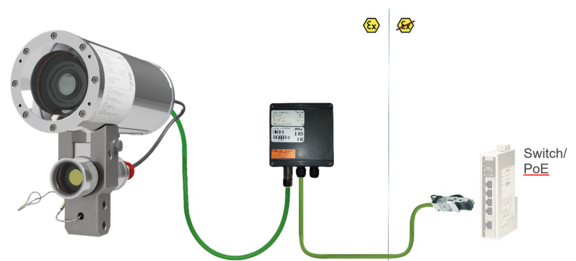
005.N = Non armoured cable - P = Plug- termination (standard) CAT6, RJ-45 network plug (heavy duty), AWG 26-22, contact assignment acc. to specification EIA/TIA-568B
T = Terminal box- termination (optional) 4 x PoE Mode A connection (camera PoE) (see electrical connection)
Electrical parameters
Power supply of the camera (PoE):
Voltage supply: PoE, IEEE 802.3af/802.3at type2 class 4
Reference voltage: +48 V DC (44...54 V DC)
Maximum power consumption: 25.5 W
Typical power consumption: 19.5 W
Connection cables
Appropriate cables & cable glands:
for this watch the following video-tutorial or the informations on the cable-page.
Attention!
- Cables and wires must comply with the requirements of the IEC 60079-0/1/7 & 14.
- The supply line must have a sufficient cross-section. The cable protection must comply with national and international regulations.
Cable glands
Camera
System cable SKD02-T --> Gland Capri ADE1F2 M20x1,5 Cap No.5 (7-12mm)
System cable ASKD02-T --> Gland Capri ADE4F Cap No.6
Declaration of conformity, Instruction Manual
Luminaire
Ölflex heat 125 ML 3G --> Ex-d gland ANACONDA Sealite for steel armouring type SU, Nickel-plated brass for 5/8"
Declaration of conformity, Instruction Manual
Protective hose ANACONDA multiflex, stainless steel armoured
Declaration of conformity, Instruction Manual
Video-technical characteristics
Other technical data
Permissible ambient temperature: -30°C ... +50°C
Protection class as per EN 60529/IEC 529: IP66/68 (test conditions 24h/3m water column at 5°C)
Housing material: Stainless steel mat. no.: 1.4404
Weight: ca. 8.4kg
Dimensions: 236.75mm x 113mm x 260mm
LED illumination
Information to liteServer Ex.micro
White light LED
A neutral white high-power COB LED with a nominal power of 12.5 W is used in this device as a radiation source for visible light. The COB LED is characterized by the following technical properties:
LED Type: COB-LED (InGaN), single phosphor dot, non-matrix arranged, divergent, non-focusing
Power consumption: 12.5W
Max. power consumption: 12.9W@24VDC
Color rendering: 440nm to 690nm
Color temperature: 5000K
Luminous flux: 1930lm
Beam angle: 90°
Dimensions (ØxH): 28 x 2.4 mm
IR LED
A SMD IR-LED with a radiance of 4120 mW is used in this device as a radiation source for visible light. The IR LED is characterized by the following technical properties:
LED Type: High Power 12W IR SMD-LED
Max. power consumption: 12.7W
Infrared centroid wavelength: 850nm
Radiation intensity (IR850): 4120mW
Beam angle: 90°
Operating hours: 50000h
Attention!
Infrared radiation may emanate from this product. Do not look directly at the operatimg lamp.
Illumination tests
The external illumination in combination with the ExCam IPM1137 ensures that you get a good image up to an object distance of 30.0m. Even at a distance of 60m, the light intensity is sufficient to be able to recognize an object in the field of vision. See the tests on the illumination of the ExCam IPM1137-LE in the Eleonore Stollen Asslar.
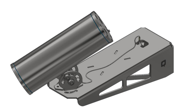
Mounting
Attachment with the Wall mount Bracket
Electrical Connection
- May only be carried out by qualified personnel!
- Ground the housing via PA-connection!
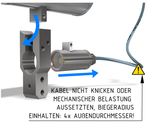
- Cabels have to be layed protected, observe bending radius!
- Electrical work inside the pressure resistant enclosure by the user are not authorized!
Terminal box Assignment
Attention
- Never open Ex-e terminal box under voltage!
- Adhere to the international installation regulations for connection chambers with increased safety (Ex-e).
- Adhere to attached seperate User Manual for the ex-e terminal box.
Connection work at the terminal box
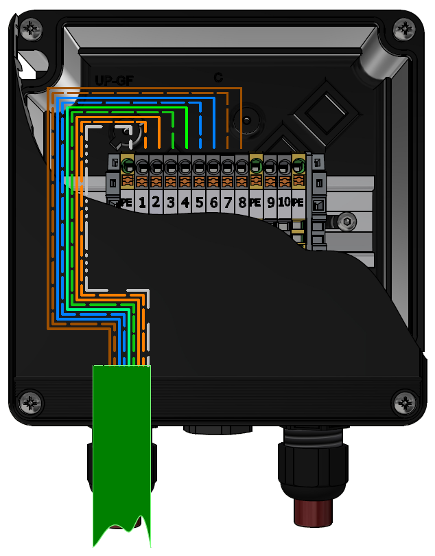
Plug Assignment
Plug assignment RJ45 plug acc. to EIA/TIA 568B
Connection work with plug
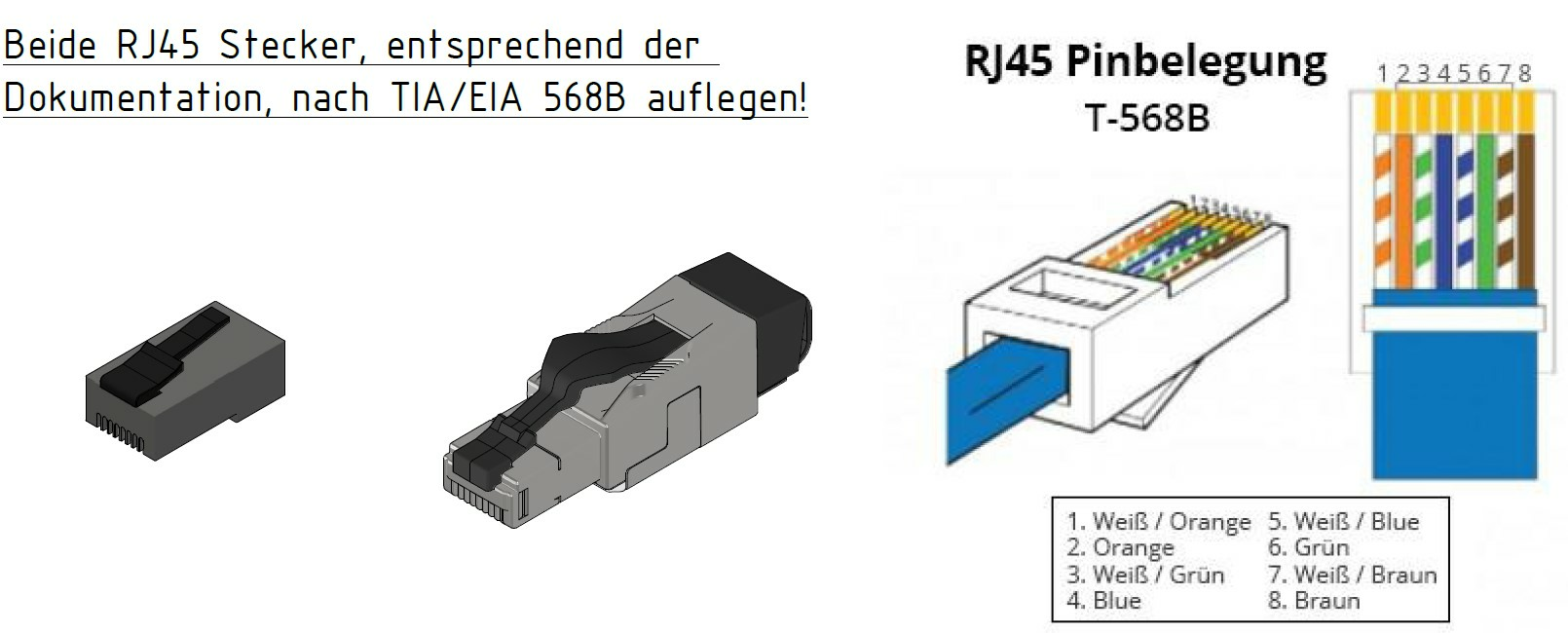
Attention!
- Use appropriate RJ45 plugs! Check the cable shielding, cross-section and the outside diameter!
- It is imperative to ensure a correct routing of the individual wires acc. to EIA/TIA-568B.
- Finally, check your network installation with a Class-D Link test.
Direct routing from the ExTB-3 into the safe area
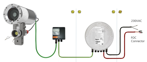
Routing via ExConnection Rail (optional accessories)
Tests prior to switching on voltage
Attention!
- Prior to starting the device, perform all tests as indicated by the national regulations. Furthermore, check the correct function and installation of the device in accordance with this User Manual and other applicable regulations.
- Incorrect installation or operation of the camera may lead to a loss of warranty!
- Do not switch on the camera at temperatures below 0°C!
Working inside the camera housing (Ex-d)
Reasons for opening the camera's housing:
- Exchange of the SD memory card
- Hardware-reset
Reasons for opening the luminaire's housing:
- Exchange of the LED-block
Important!
- MAY NOT BE OPENED IN HAZARD AREAS
- Depending on classification of hazard areas, it is imperative to obtain a work approval first!
- Prevent explosive atmosphere!
- Do not damage the thread surface of the flame-proof gap and the housing seals!
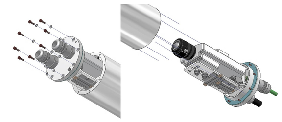
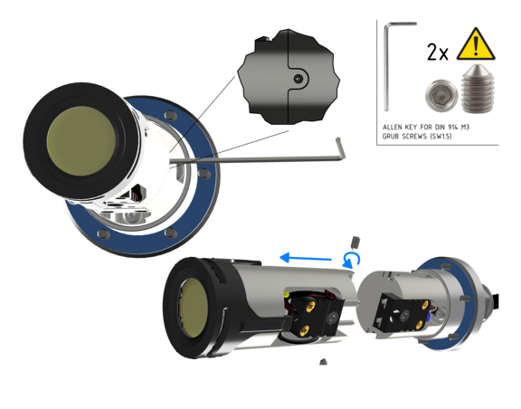
Dismantling the liteServer and the cam adapter
In order to open one of the two housings, the camera and light must first be separated from each other. To do this, proceed as follows:
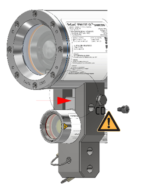
Loosen the M6 cylinder head screw and pull the liteServer forward slightly.
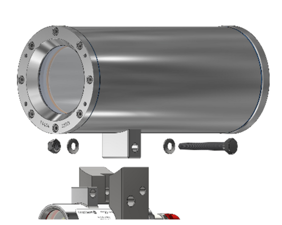
Remove M8 hexagon screw (wrench size 13). Attention: Do not lose the washer.
Remove cam adapter; Pull the liteServer backwards out of the adapter opening.
Opening the camera housing
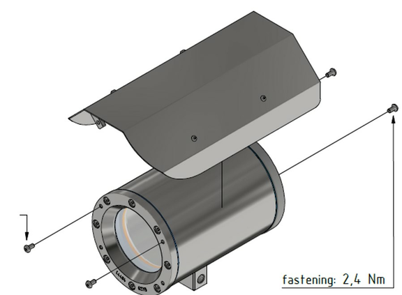
Remove weather protection roof, if camera is equipped with one.
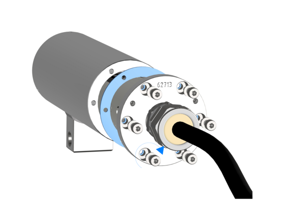
Loosen the eight screws on the rear side of the cable and power supply flange. Never open the front-side sight-glass flange.
Carefully pull out the cable and supply flange to the rear, as straight as possible. Because of negative pressure, it may be difficult to remove the flange. The cylindrical clearance fit (H8f7 - DIN ISO 286) of the camera body and flange may not be tilted! Risk of damage to the flame-proof gap (DIN EN 60079-1:2012)!
Attention!
The mounting adapter with the housing’s PTC heater, camera module and optics, as well as the temperature control, and (if applicable) auxiliary relays and terminal block are fixed on the cable and supply flange. Dealing with these components, too, you have to work very carefully and precisely in order to avoid canting and damage to the in-built components! Caution: do not touch the cylindrical fit surface with your skin or clothes! On the surface, there is oil lubricating paste to protect the surface against fretting corrosion and mechanical stresses. When you open the housing, pay attention that you do not damage the GYLON® flat seal (blue, RAL5012) and do not make it dirty! The flat gasket is loosely attached to the cable and power supply flange. It is fixed only by the bolted connections!
Opening the luminaire housing
For opening the liteServer®’s pressure-resistant stainless steel housing T07 VA0.1.K1.BOR, it is mandatory to follow the step-by-step instructions as stated in the T20 Ex installation manual!
Loosen the six M3 cylinder-head hexagon screws (DIN 912/ ISO 4762) together with their spring rings (DIN 127A) on the rear side of the cable and power supply flange. Caution: do not touch the screw threads with your skin or clothes! On the threads, there is LOCTITE® 243™ (chemical basis is dimethacrylate ester) applied to prevent the bolted connection from unintentional loosening because of impacts and vibrations.
Carefully pull out the cable and supply flange to the rear, as straight as possible. Because of negative pressure, it may be difficult to remove the flange. The cylindrical clearance fit (H8f7 - DIN ISO 286) of the housing body and flange may not be tilted! Risk of damage to the flame-proof gap (DIN EN 60079-1:2012)!
Caution: do not touch the cylindrical fit surface with your skin or clothes! On the surface, there is oil lubricating paste to protect the surface against fretting corrosion and mechanical stresses.
When you open the housing, pay attention that you do not damage the GYLON® flat seal (blue, RAL5012) and do not make it dirty! The flat gasket is loosely attached to the cable and power supply flange. It is fixed only by the bolted connections!
Pull out the luminaire carefully and pay attention not to clamp the cables.
Attention!
Beware not to damage the surface of bore hole and shaft (fit) at the flame proof gap preventing the transmission of ignition.
Please make sure not to damage housing sealings and to keep them clean.
Removing / inserting a SD memory card
The ExCam IPM1137-LE has a slot for a micro SDHC memory card (card not included). Saved video files can be played and deleted via the web interface. They are also available in a download list. Moreover, the videos available in the memory card can also be accessed via FTP server in the network.If the memory card has to be replaced by the user, it should be, as far as possible, empty and pre-formatted with an ext4 or vFAT file system.
When touching electrical components, observe potential equalization (grounding of the body): carry electrostatic-discharge clothes, a PE wristband etc.!
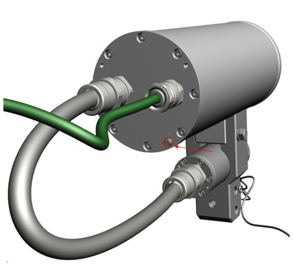
Hardware Reset
To set all the parameters of the ExCam IPM1137-LE (including the IP address) to default values, you should run a hardware reset. The parameters can be reset via the web interface or manually. If the camera placed in the network can no longer be reached or its state is uncontrollable, the reset should be per-formed manually. To do so, proceed as follows:
- Disconnect the camera installation module (Axis M1137 MKII) from the power supply.
- Press and hold the control button (see the illustration below) and, at the same time, connect the system to the voltage supply (PoE).
- Hold the control button pressed for about 30 seconds.
- Release the control button. After about a minute, the AXIS M1137 MKII will return to factory defaults. If there is a DHCP server in the network, the IP address will be the following: 192.168.0.90 (subnet masking 255.255.255.0).
- IP address and password can be redefined. If the hardware reset is not satisfactory or the network camera shows serious conflicts or does not work as usual (errors in the browser visualisation, frozen images, control commands no longer processed, slowing down of the system, etc.), it may be necessary to re-install the current firm-ware, or to install an update.
Exchanging the illuminant
The illuminant should only be exchanged if it is defect. It must be replaced by an original spare part of the same model. In this special case it is allowed and necessary to open the Ex d housing. All required steps are described in this user manual; the descriptions stated in the T20 liteServer® Series Ex installation manual have to be observed!
Perhaps our video will help you: "Replacing the illuminant of liteServer Ex.micro"
To replace the LED-block the 2 grub screws on the side must be carefully loosened. The LED block is plugged in and can easily be removed after loosening the grub screws. Seperate it at the plug contacts.
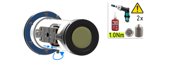
Insert the plug of the new LED replacement block into the connection socket oft he housing flange. Make sure that the plug contacts and contact surface of the aluminium heat sink are clean and undamaged. After successfully replacing the LED block, the grub screws must be tightened again. Only use new, original grub screws. Tightening torque is 1.0 Nm! Loctite 243 may be used for screw locking.
When touching electrical components, potential equalization (grounding of the body) has to be observed (ESD clothing, PE wristband etc.)!
When closing the housing, the cable routing has to be observed! In order to avoid collisions and mechanical strain within the closed housing as well as to observe the necessary bending radius, the cable has to be looped.
Closing of the pressure-resistant housings
For closing the housing, proceed in reverse order as when opening. Use exclusively original screws included in the supply. The cable and power-supply flange (K1) is fixed by 8 cylinder-head screws M4*0.7 (ISO metric right-turning) with 12 mm thread length (DIN 912/ ISO 4762, grade 6g). Materials of bolted connections are identical to the pressure-resistant stainless steel housing (standard material no. 1.4404 AISI316L). Check whether the threaded holes are undamaged and clean. Before closing, it is also absolutely imperative to check the flame-proof gap (circular cylindrical fit).
Attention!
If any mechanical damages occurred to the fitting gap, it is no longer allowed to use the housing!
Attention!
Do not lock-in any foreign objects in the housing.
Attention!
Insert the flange to reach the end position, in order to ensure ignition protection and the protection level (IP) of the housing.
Dismantled screw locks (spring washers DIN 127A) must be used again. The GYLON® gasket must be used in undamaged condition, according to the flange hole pattern, and placed between the flange and the hull. The lateral position of the flat surface / contact surface is arbitrary. If, when closing the housing, you see that the surface of the fitting gap is dirty or insufficiently lubricated, clean it with a clean cloth and de-grease it with a suitable cleaning agent. Then re-grease it with lubricant suitable for this specific application (e.g., Molykote® P-40 gel for standard applications or special grease OKS 403 in the event of heavy seawater influence).
Closing of the camera housing
Cylinder-head bolts for explosion-proof connection of the camera body with the flange component must always be tightened at a 3 Nm torque - crosswise and evenly! Use Loctite.
Closing of the luminaire housing
Cylinder-head bolts for explosion-proof connection of the luminaire body with the flange component must always be tightened at a 1.2 Nm torque - crosswise and evenly! Use Loctite.
Network Access, Installation and Comissioning
Initial start-up
https://help.axis.com/de-de/axis-m2036-lehttps://help.axis.com/axis-m1137-mk-ii
M11 Mk II Series - User manual (axis.com)
Applicable net frequency: 50Hz or 60Hz
Carry out other net frequency: menu System Options > Advanced > Plain Config
User: root
Password: root
Browser support
A list of the currently supported web browsers, operating systems, required add-ons, etc. can be viewed at:
https://help.axis.com/access-your-device
https://www.axis.com/support
Allocating IP Adress
The ExCam IPM1137-LE is intended for use in an Ethernet network and requires an IP address to access and control it. In the most today's networks, a DHCP server is integrated. This server automatically assigns an IP address. If there is no DHCP server available in the network, the IP default address of ExCam IPM1137-LE is "192.168.0.90" (subnet masking 255.255.255.0). With the "AXIS IP Utility", it is possible to determine the IP address under Windows; the included USB stick contains this application.
https://www.axis.com/support/tools/axis-ip-utility
If it is not possible to assign the IP address, it might be necessary to change the firewall settings! The "AXIS IP Utility" tool automatically recognizes all ExCam devices and visualises them in the device list. It can also be used to manually assign a static IP address. For this purpose, the ExCam IPM1137-LE network camera has to be installed in the same physical network segment (physical subnet) as the computer on which the AXIS IP Utility is running. The network signature of ExCam IPM1137-LE is "AXIS M1137 MKII". MAC address and serial number for clear device identification are also detected and displayed.
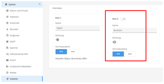
Controlling the light via the camera
The LED spotlight can be switched on and off manually using the button marked in the picture, or activated for an interval of up to 60s.
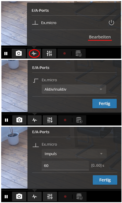
To access the I/O port directly, go to the Menu System > Accessory.
It is also possible to use events and rules.
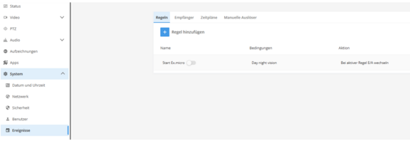
Klick the following link to get more information of how to install rules for events:
AXIS M1137 Mk II Box Camera Benutzerhandbuch
Klick the following link to get more information about events:
Accessories


Other Accessories
Hinge attachement, Thermo isolator, Twin-adapter, SuperClamp-Mounting adapter