Useful information for operators and installers of potentially explosive systems with regard to explosion-protected luminaires
Within the framework of market research conducted on explosion-proof LED luminaires, it was discovered that different manufacturers apply different standards for their products, both in the sphere of ATEX requirements and within the IECEx scheme. This does not constitute a peculiarity on initial consideration, because explosion safety can be achieved with the aid of different protection systems, the bases of which are provided by the respective standards. Conspicuous, however, is the application of "IEC/EN/DIN 60079-28: Protection of equipment and transmission systems using optical radiation", hereafter abbreviated to 60079-28. Some manufacturers apply this standard to LED luminaires, while other manufacturers do not.
We investigated the question of why this discrepancy arises. The application or lack of application of 60079-28 obviously leads to different equipment standards, which in turn raises the following questions:
- Why do some manufacturers apply 60079-28, while others do not?
- How do EX LED spotlights differ from EX halogen spotlights for example?
- Are EX spotlights safe if they have not been assessed according to the criteria of 60079-28?
Detailed research of the standards is necessary in order to answer the first question.
The second and third questions both call for technical examination of the equipment available on the market. We make an initial attempt at such an examination.
You can find more information on this topic in our video “Ex-Scheinwerfer sicher machen: liteServer Technologie - Lichtenergie und Schwarzkörperabsorption”
Explosion protection parameters
Equipment was analysed for the following application parameters:
ATEX equipment group: IID and IIG
ATEX category: 2
Equipment protection level: Gb and Db
Temperature class: T4 to T6
Status quo of the 60079 series of standards
General requirements: IEC 60079-0:2017
In the standard "Explosive atmospheres - Part 0: Equipment - General requirements (IEC 60079-0:2017)", clause "6.6.4 Lasers, luminaires and other non-divergent continuous wave optical sources " contains the following sentence:
"The requirements for lasers, luminaires and other non-divergent continuous light sources such as LED luminaires, torches and optical fibre transmitters/receivers are described in IEC 60079-28."
According to inquiries, all companies that do not apply 60079-28 refer to this clause. Logically, the statement in the standard conversely reads:
Requirements for ... divergent continuous light sources are not described in 60079-28.
This is how manufacturers responded to our inquiry in this regard:
„…Our illuminator is not compliant with 60079-28 because this type of product does not fall under this certification. Let me explain: The 60079-28 is applied to converging light sources where the light is focused on a single point included in the classified area. In our illuminator, the EN/IEC/UL 60079-28 standard is not applied as the light beam of our spotlight is considered divergent…“
According to the argument, 60079-28 is therefore not applied for divergent light, which in turn means that the emitted light output of such luminaires is not subject to any evaluation. The accreditation bodies of the companies specified have followed this logic. The question of whether this makes technical sense will be evaluated below.
Chapter "26.5 Thermal tests" of IEC/EN/DIN 60079-0 also deals with this. There is no provision in the standard that requires an evaluation of the thermal heating of a "black absorber" in the light beam of explosion-protected luminaires.
In DIN EN IEC 60598-1 "Luminaires - Part 1: General requirements and tests", the following is described in chapter 12.4 Heating test (normal operation):
"...During normal operation, no part of the luminaire (including the lamp), or the connecting wires within the luminaire, or the mounting surface shall reach a temperature which would impair safety. In addition, parts intended to be touched, handled, adjusted or held in the hand when the luminaire is at operating temperature must not become too hot for this purpose.
Luminaires must not heat illuminated objects to an inadmissible degree..."
Unfortunately, DIN EN IEC 60079-0 does not reference IEC EN DIN 60598. However, this, as well as a substantiation of the term "inadmissible", would be necessary to counter the explosion risk of the "hot black absorber".
Optical radiation: IEC 60079-28:2015/2019
The standard: "Explosive atmospheres - Part 28: Protection of equipment and transmission systems using optical radiation (lEC 60079-28:2015); chapter 1: "Scope" comes to the following conclusion:
"... Continuous divergent LED light sources ... are not exempt from the application of the standard (60079-28) because of the uncertainty of potential ignition concerns regarding high irradiance...."
An evaluation of LED spotlights is therefore required in this case. The IECEx committee published a corresponding interpretation paper in 2019 as a result of this contradiction.
In the document: "EXPLOSIVE ATMOSPHERES - Part 28: Protection of equipment and
transmission systems using optical radiation, INTERPRETATION SHEET 1", the following question is posed:
„…When should the requirements of IEC 60079-28 be applied to Ex Equipment, including Equipment assemblies and Ex Components that include an optical radiation source based on Subclause 6.6.4 “Lasers, luminaries, and other non-divergent continuous wave optical sources” in IEC 60079-0:2017 (Edition 7)?...“
The answer clearly verifies the right of non-users:
„…This standard does not apply to:
…2) divergent light sources or beams, where light is not focussed within the hazardous area…“
Status quo of the standards situation
As of today, an analysis of the temperature of a black absorber in the light beam is not required in the measurement and evaluation of the maximum surface temperature of the equipment.
According to current standards, the light output of an EX luminaire does not have to be evaluated with respect to a potential explosion hazard.
Are EX spotlights safe?
Light transports power. This is very apparent with high-power lasers; in modern metalworking, for example, lasers are used to cut steel. During this process, temperatures are reached that are beyond the ignition temperatures of gases and it becomes instantly apparent that such "laser cutting" in an EX zone represents an ignition hazard.
Furthermore, it is also clearly evident that a small status LED does not emit enough light power to generate an ignition source in the hazardous area.
An EX spotlight is neither a high-power laser nor a small status LED. It ranks somewhere between these two extreme examples in terms of the power of its light output as well as its beam angle, and the following questions arise accordingly:
When is the light output power of an EX spotlight still safe?
When does this output power become dangerous?
Potential ignition sources
For light in the wavelength spectrum from 380nm to 10µm, IEC 60079-28 defines the following ignition mechanisms in chapter 1 "Scope":
"Optical radiation is absorbed by surfaces or particles, which can heat up as a result of this, and - under certain circumstances - reach a temperature that can ignite a surrounding explosive atmosphere."
"In special cases, which arise only rarely, the direct laser-induced breakdown of a gas at the focus of a powerful beam and generation of plasma or a shock wave can potentially act as an ignition source. These processes can be favoured by a solid that is close to the breakdown point."
This paper only examines the first point. It is not possible to examine plasma ignitions due to lack of laboratory facilities.
The black absorber
The ignition mechanism of the "hot black absorber" described above assumes the following scenario:
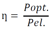
An EX spotlight is supplied with electrical power (Pel.). Depending on the illuminant used and its efficiency (ƞ), a portion of the power that is fed in is converted into heat; this power is called power loss (Pv.). The remaining power is converted into light (Popt.). In our scenario, this optical power (Popt.) hits the black absorber at the distance (s) from the exit surface at the radiator. Due to the absorption, the black absorber heats up and emits this power again in heat (PSA.). The black absorber has an absorption level of 100% by definition. As such, all light output (Popt.) is converted into heat. In our first approximation we therefore define: Popt. = PSA. When converted into practice, this would be equivalent to a dark layer of dust near the light-transmitting surface of the spotlight.

The ignition hazard - that of both the spotlight and the black absorber - results from the maximum surface temperature (Tsur. max.). This maximum surface temperature is a clearly defined term in explosion protection and must be determined, documented and labelled as part of the equipment test in accordance with 60079-0. A user must be clearly able to match the temperature class of the equipment with the ignition temperature of the gases in their installation; the same applies to glow and ignition temperatures of combustible dusts. The maximum surface temperature of a piece of equipment occurs at the maximum permissible ambient temperature (Tamb. max.). For example, Manufacturer_2 specifies T6 (85°C) for gases and Tsur max. = +82°C for dusts on the type plate for Luminaire_2. This will be further investigated later on in this paper. The "product promise" is:
"Our spotlight never gets hotter than Tsur. max. = +82°C at its hottest point at the ambient temperature (Tamb. max.) +48°C."
While the maximum surface temperature of the spotlight is critically examined, according to the situation per the current standards for divergent EX luminaires no evaluation of the optical performance (Popt.) takes place, and therefore no measurement and evaluation of the maximum temperature of a black absorber (TSA.).
Efficiencies of illuminants
The efficiency (ƞGlueh.) of an incandescent bulb is about 5%. This means that only a fraction of the power (Pel.) supplied is converted into light, the remaining 95% is lost as waste heat (Pv.) in the environment. As such, incandescent bulbs achieve a luminous efficacy of 10 to 15 lumens/watt.
The efficiency of a halogen lamp (ƞHal.) is only slightly better at about 10%. Here, too, almost 90% of the power input (Pv.) is lost as waste heat in the environment and the lamps achieve a luminous efficacy of 15 to 20 lumens/watt.
The theoretical efficiency of cool white LEDs is 100%, which corresponds to 350 lumens/watt. However, this efficiency is not achieved in practice because ballast electronics, filters and optics generate power loss (Pv.). Nevertheless, commercially available LEDs already have an efficiency (ƞLED) of 40%, and the trend is rising. LEDs are therefore by far the most effective light source.
Illuminant | Efficiency (ƞ) in % |
Light bulb | 5 |
Halogen light | 10 |
LED | 40 |
Example calculation of LED efficiency:
The lamp delivers 1500 lumens with a power consumption of 12 watts
1500 lumens: 12 watt = luminous efficacy 125 lumen/watt
Physical maximum (100% efficiency): 350 lumens/watt
125 lumens/watt: 350 lumens/watt = 0.36 corresponds to an efficiency of 36 percent.
Remark:
Only in the following schematic diagrams do we define the efficiency of halogen luminaires as 25% (ƞHal.) to illustrate the problem = 25% and the efficiency of LEDs as (ƞLED) = 75%. All measurements and investigations work with actual light sources and their actual efficiencies.
Considerations for EX halogen spotlights
The efficiency (ƞHal.) of halogen spotlights is comparatively low relative to the efficiency of LED lamps (ƞLED). For the schematic representation we assume that ƞHal. is 25%.
It follows that most of the power fed in is power loss. This is dissipated in the form of heat directly at the equipment, i.e. at the spotlight. Succinctly put: The equipment surface becomes hot. This leads to manufacturers of EX halogen luminaires usually specifying the temperature class T4 or T3.
The "product promise" for T4 is:
"Our spotlight never gets hotter than Tsur. max. = +135°C at its hottest point at ambient temperature (Tamb. max.)."
In our schematic example, the optical power is only 25% of the feed-in power. Accordingly, only this comparatively low optical power (Popt.) is available to the black absorber for heating (PSA).
As long as the temperature of the black absorber is lower than the stated maximum surface temperature of the equipment, there is no danger of explosion.
Considerations for EX LED spotlights
The efficiency of LEDs (ƞLED) is comparatively high relative to the efficiency of halogen lamps (ƞHAL). For the schematic representation in the following picture, we assume that ƞLED is 75%.

It follows that most of the power fed in is converted into light power (Popt.). If this is absorbed by a black-body, it is released into the environment in the form of heat output (PSA). Only a small portion of the power fed in remains in the enclosure and generates heat there (Pv.).
The spotlight itself remains relatively cold; if LEDs had an efficiency of 100%, the spotlight would not heat up at all. Its maximum surface temperature (Tsur. max.) would be equal to the ambient temperature (Tamb).
The high efficiency and the fact that the spotlights remain relatively cold mean that their manufacturers usually mark the temperature classes T5 or T6. In terms of the standards, this is correct: Only the maximum surface temperature of the equipment, and not that of a black absorber in the light beam, is evaluated.
The "product promise" for T6 LED spotlights is:
"Our spotlight never gets hotter than Tsur. max. = +85°C at its hottest point at ambient temperature (Tamb. max.)."
However, the optical power in our schematic example is 75% of the feed-in power and this power is available to the black absorber for heating (PSA). The black absorber may therefore be significantly hotter than the maximum surface temperature on the equipment itself in the case of high-efficiency light sources (LED).
With high-efficiency LED spotlights, the maximum surface temperature does not occur on the equipment itself, but on the black absorber in the luminous flux. In the case of EX LED spotlights, this will be significantly hotter than the measured and marked surface temperature of the equipment. This in turn results in an ignition hazard, regardless of the hot surface of the EX luminaire, which is currently not taken into account in the standards.
Multi LED arrays
If we simplify the geometry of multi-LED arrangements to just two LEDs arranged next to each other, the following example dimensions result, e.g. for measured luminaire below, as shown in the following figure:
Beam angle of the LEDs (with lens and/or reflector): 10°
Distance between the LEDs: approx. 16 mm
Distance to the intersection of both light beams: approx. 90 mm
Cold spots
"Cold spots" occur in the areas that are not reached by light. These "cold spots" are not "irradiated". Black absorbers are not able to convert light output into heat output here, because the luminous flux does not reach the black absorbers.

Group 1 hot spots
Group 1 hot spots arise in the centre of the light beam of an LED, immediately after it emerges from the protective enclosure. The energy density is highest here at "acute" radiation angles. Due to the divergent character of the light beam, as well as the absorption of light energy by particles in the atmosphere, the energy density decreases with distance from the exit point. The light energy is greatest in the middle of the beam.
Group 2 hot spots
Group 2 hot spots occur when at least two LEDs are emitting (in practice, these are matrix or ring arrays). From the point of intersection of the light beams, the light energy of both beams hits a potential absorber. Whether the effect of this output consolidation outweighs the losses up to this point is determined by the geometry of the construction; in particular the beam angle. The more "obtuse" the beam angle, the earlier and therefore more loss-free and energy-rich the two light beams meet. In contrast to group 1, hot spots of group 2 can also occur behind the protective enclosure.
Correlation of the hot spots to the ambient temperature
Neither the hot spots of group 1 nor the hot spots of group 2 are theoretically dependent on their ambient temperature. The light energy is converted into heat energy.
The temperature at the black absorber is therefore only dependent on the light energy and as such on the power of the LED and its temperature-dependent efficiency.
In a vacuum and with a small black-body, the following applies:
Plight is proportional to TSA
In practice, we have neither vacuum nor small black absorbers. Nonetheless, we were able to prove the law by heating the black-body to the maximum permissible ambient temperature of the equipment and switching on the LEDs cooled and uncooled: Cold LEDs heat up the black absorbers more than warm LEDs, because their efficiency is higher at colder temperatures.
Further considerations for the black absorber

In tests with the above PT100 sensors in air, it was discovered that the absorption temperature of the sensor depended on whether its front side was irradiated with an area of 8 mm2 or its underside with an area of 16 mm2. The measurement results with an absorption area of 16 mm2 were significantly higher than the temperatures that could be measured with an absorption area of 8 mm2 .
This observation raised the following questions:
What is the relationship between the "type of light beam", the black absorption surface and its temperature?
What potential absorption surfaces can be found in practice?
Is the thermal conductivity of the black absorber significant?
How can one or more "worst-case" measurements be performed?
The absorption surface
First of all, it seems reasonable to assume that the larger the absorption surface, the higher its temperature. If we look at the homogeneous and - with an initial approximation - parallel light beam, this assumption is correct: The greater surface area, the greater the light energy that can be absorbed, as can be seen in the evaluation below.
However, this theory of "the-bigger-the-hotter” is not valid without qualification. If the absorption surface has good heat conduction properties, temperature averages can be achieved with larger surfaces. This occurs, for example, when the absorption surface is on a plane with cold spots. In the case of multi-LED arrays, small, thermally insulated black absorbers measure significantly higher temperatures than a large thermally conductive absorber located on the cold spot plane. The same applies to spotlights with reflectors where partial beam consolidation may occur.
The following test absorbers were constructed:

The material used was thermally conductive aluminium, which was painted with black matt paint on the absorption surface. The black absorbers were placed in the light beam and the distance to the light source was varied:

Distance/ mm | Max. | Max. | Temp. of the black-absorber | Temp. of the black-absorber 5qcm in C° | Temp. of the black-absorber |
0 | 40 | 200 | 209,0 | 228,0 | 229,8 |
4 | 40 | 200 | 199,0 | 227,0 | 223,4 |
7 | 40 | 200 | 198,0 | 232,0 | 238,4 |
12 | 40 | 200 | 190,0 | 238,2 | 234,1 |
18 | 40 | 200 | 207,8 | 238,5 | 239,4 |
34 | 40 | 200 | 180,0 | 205,6 | 213,4 |
46 | 40 | 200 | 169,0 | 177,1 | 189,0 |
Black absorber with different surfaces

The question raised above: "What is the relationship between the "type of light beam", the black absorption surface and its temperature?" can be answered as follows, based on the results of the experiment:
The following applies in a homogeneous, slightly divergent and parallel light beam that luminaires the entire black-body:
The larger the surface of the black absorber, the greater its surface temperature.In reflector luminaires and multi-LED arrangements, small and thermally insulated black absorbers heat up strongly.
The maximum temperature of the black absorber consequently depends on the power and the type of light beam or beams, the thermal conductivity, the surface area as well as the position of the black absorber.
Potential absorption surfaces in practice
In practice, the following absorption events may occur:
Conductive dark smear layer on the pane, e.g. oil.
Insulating dark smear layer on the pane, e.g. plastic
Conductive dark layer of dust/dirt on the pane
Insulating dark layer of dust/dirt on the pane
Free-floating particle in the light beam
Scenarios 3 and 4 are certainly most common in practice.

Measurement series
The actual temperature on a black absorber is to be measured for a series of spotlights with halogen and LED light sources. The measurement apparatus consists of the spotlight and a black absorber in which six PT100 temperature sensors are embedded. The distance (s) between the translucent opening of the spotlight and the black absorber is varied. The first measurement takes place directly at the translucent opening of the spotlight. The distance (s) between the spotlight and the black absorber is then increased until the temperature of the black-body reaches a stable value.


The primary questions with respect to the experiments are:
Does the measured temperature of the black-body exceed the specified temperature class (gas or dust) of the spotlight (EX equipment)?
How and when does the divergent light beam affect the measured black-body temperature?
How do the different efficiencies (ƞ) affect the relationship between black-body temperature and maximum surface temperature of the equipment?
Is the black-body temperature relative to the ambient temperature of the equipment (spotlight)?
Halogen spotlight Manufacturer_1 Luminaire_1
The halogen spotlight has the following technical and explosion protection data:
| Manufacturer: | Manufacturer_1 |
| Type: | Luminaire_1dH |
| Construction type: | Halogen spotlight with reflector |
| Power supply: | 24VDC |
| Power consumption: | 50W |
| ATEX certificate | LCIE xx ATEX xxxx |
| IECEx certificate | n.a. |
| EX marking GAS | Ex d IIC T4 |
| EX marking DUST | Ex tD A21 IP65 130°C |
| Permissible ambient temperature | -20°C <Tamb< +40°C |


Due to the very high temperatures at the black absorber, all measurements were carried out at room temperature (20°C). A temperature difference of 20K was then added to the measured values to represent the conditions at Tamb max= 40°C. We are aware that this simplification is a rough approximation. This is acceptable because this is a qualitative measurement. +/- 10K only play a minor role in the results determined below.

Hot spot measurements on the black absorber
The following temperatures were measured on the black absorber depending on the distance to the equipment:
Distance | Maximum ambient temperature in °C | Maximum surface temperature in °C | Black-body |
0 | 40 | 130 | 210.0 |
18 | 40 | 130 | 173.6 |
23 | 40 | 130 | 147.4 |
30 | 40 | 130 | 139.6 |
36 | 40 | 130 | 129.9 |
41 | 40 | 130 | 118.9 |
58 | 40 | 130 | 113.0 |
67 | 40 | 130 | 109.8 |
72 | 40 | 130 | 101.1 |
90 | 40 | 130 | 98.2 |
116 | 40 | 130 | 92.1 |
160 | 40 | 130 | 85.9 |
310 | 40 | 130 | 72.5 |
450 | 40 | 130 | 65.0 |
Tab.: Hot spots on the black absorber Luminaire_1

Impermissible temperature range
In the beam of the halogen luminaire, inadmissible surface temperatures occur on the black absorber and the light output heats it to over 210°C at an ambient temperature of +40°C. A black absorber in the immediate vicinity of the light exit aperture heats up to 210°C. As such, it becomes 75K hotter than the maximum surface temperature of the equipment and only after a distance of 32 mm does the black-body temperature fall below the specified maximum ambient temperature of +130° C.
Hot spots
It is noticeable that the hot spot temperature drops more slowly depending on the distance to the spotlight. If a linear recursion line were applied, the negative slope would be smaller for halogen spotlights than for LED spotlights.
Two effects combine here:
The optical energy in the light beam.
The significantly higher convection radiation of halogen spotlights compared to LED spotlights.
The effect of the thermal convection can be demonstrated by comparing how quickly the black absorber cools down. While the black absorber in the vicinity of hot halogen spotlights requires almost an hour to cool down to room temperature after these are switched off, cooling takes place much faster with "cold" LED luminaires.

Cold spots
"Cold spots" occur in the areas that are not reached by light. No cold spots could be detected with our measurement apparatus described above; light beams from halogen lamps with reflectors do not generally exhibit cold spots.
Group 1 hot spots
Hot spots of group 1 result at a distance of up to approx. 30 mm in front of the translucent opening. This results in an impermissible operating range.
Group 2 hot spots
Hot spots of group 2 could not be measured directly. In the case of halogen spotlights with reflectors, there can be at most one hot spot 2 outside the enclosure due to the optical geometry of the luminaire: The focal point of the reflector. We can only speculate here because the geometry of the reflector is unknown. The measurements show a slight increase at a distance of roughly 23 mm, which could indicate a focal hot spot.
Test result
Manufacturer_1 halogen spotlight Luminaire_1 cannot be rated as safe without limitations.
The temperature at the black absorber is approx. 75K higher than the specified maximum surface temperature of the equipment close to the light exit of the spotlight. Safe conditions are only achieved approx. 32 mm behind the optical opening of the equipment.
LED spotlight Manufacturer_2 Luminaire_2
The LED spotlight has the following technical and explosion protection data:
| Manufacturer: | Manufacturer_2 Ltd. |
| Type: | Luminaire_2 |
| Construction type: | LED matrix |
| Power supply: | 230VAC |
| Power consumption: | 68W |
| ATEX certificate | CML xx ATEX xxxx |
| IECEx certificate | IECEx CML xx.0001 |
| EX marking GAS | Ex eb mb IIC T6 Gb |
| EX marking DUST | Ex tb IIIC T82 ºC Db |
| Permissible ambient temperature | -52°C <Tamb< +48°C |

Hot spot measurements on the black absorber
The following temperatures were measured on the black absorber depending on the distance to the equipment:
Distance | Maximum | Maximum | Black-body |
0 | 48 | 82 | 101.6 |
1 | 48 | 82 | 101.1 |
2 | 48 | 82 | 101.4 |
2.9 | 48 | 82 | 100.1 |
4 | 48 | 82 | 90.3 |
5 | 48 | 82 | 85.8 |
6 | 48 | 82 | 87.6 |
7 | 48 | 82 | 87.3 |
8 | 48 | 82 | 83.5 |
9 | 48 | 82 | 85.1 |
10 | 48 | 82 | 85.3 |
11 | 48 | 82 | 82.3 |
14 | 48 | 82 | 80.1 |
15 | 48 | 82 | 72 |
35 | 48 | 82 | 55 |
60 | 48 | 82 | 48 |
Tab.: Hot spots on the black absorber LUMINAIRE_2

Impermissible temperature range
Impermissible surface temperatures occur on the black absorber in the beam of the LED. The light output heats the black absorber to over 100°C at an ambient temperature of +48°C. A black absorber close to the spotlight (< approx. 14 mm) would ignite a carbon disulphide atmosphere (T6).
Only from a distance of 14 mm does the black-body temperature fall below the specified maximum ambient temperature of +82°C.
Hot spots
It is noticeable, in particular in the immediate vicinity of the LED matrix, that the temperature measurement on the black absorber is very dependent on the position of the PT100 sensor. Only after approx. 90 mm do all sensors reach the same measured values and only from this point onwards can a homogeneous and divergent light beam be assumed as an approximation.
Two effects combine here:
The beam energy decreases with the distance to the LED.
The light cones cross each other.

Cold spots
"Cold spots" occur in the areas that are not reached by light. In our measurement apparatus above, these are sensors 3, 5 and 6. These sensors are not "irradiated" and are not able to convert light output into heat output because the luminous flux does not reach these sensors. Consequently, these sensors only heat up through the convection heat of the enclosure. With values between 81.3°C and 82.9°C, these sensors measure the exact maximum surface temperature specified by the manufacturer.
Group 1 hot spots
Group 1 hot spots arise in the centre of the light beam of an LED, immediately after it emerges from the protective enclosure. The energy density is highest here at "acute" radiation angles. Due to the divergent character of the light beam, as well as the absorption of light energy by particles in the atmosphere, the energy density decreases with distance from the exit point. In our measurement apparatus above, sensors 1, 2 and 4 are at different positions of the same light beam. The light energy is greatest in the middle of the beam.
Remark: The deviations of the measurement results from the theoretical (exponential) course can be explained by the fact that the measuring sensors were only aligned by hand. The measurements therefore show absorption temperatures in the centre of the light beam at some points, and absorption temperatures at the edge of the light beam at other points.
Group 2 hot spots
Hot spots of group 2 could not be measured. The light energy at a distance of 90 mm is so low that temperature peaks could not be measured here.
Test result
Manufacturer_2 LED spotlight LUMINAIRE_2 cannot be rated as safe without limitations.
The temperature at the black absorber is approx. 20K higher than the specified maximum surface temperature of the equipment close to the light exit.
Conclusion
The current standards permit the standard-compliant development and production of unsafe EX spotlights. The light energy and its black-body absorption would not be considered in any of the luminaires measured.
The ignitable optical power is not only dependent on the convergence, homogeneity or divergence of the beam, but in particular on the light energy as well as the construction of the luminaire. However, this is not taken into account or evaluated.
We were able to demonstrate that the EX spotlights on the market are unsafe. As the efficiency of LED lamps improves, the risk increases.
We think it would be sensible and safe to include optical emitted power in luminaire risk assessments - be it to:
include the light beam in the heating measurement, or
additionally postulate regulation 60079-28 for EX spotlights.
We consider the first option to be most expedient and we would recommend a two-part test procedure:
In order to rule out the possibility of the pane reaching ignitable temperatures due to contamination, we suggest extending the measurement of the maximum surface temperature to include the measurement at the black absorber in front of the light exit aperture. The surface of this black absorber facing the light source should be black and heat conductive. It should be positioned at a distance of roughly 1 mm from the optical aperture and should not be mechanically connected to the enclosure parts. The surface of the absorber should correspond to the surface of the light beam(s). The temperature measured in this way should be included in the evaluation of the temperature class in the same way as the surface temperature of the enclosure.
With multi-LED arrays or reflector luminaires, there is a risk of hot spots in groups 1 and 2. These are much more difficult to measure. It is necessary to determine the extent to which this is required. The emergence of the hot spots was verified in this paper. The question is: How great is the probability that particles floating freely in space are sufficiently stable in terms of their position that they can be heated to the point of ignition. Such a scenario would be conceivable with coal dust in pits or in dusty atmospheres.
A sensor matrix is recommended to facilitate detecting hot spots of groups 1 and 2, e.g. black PT100 sensors, mounted on a non-heat conducting circuit board (SMD or classic). The finer the matrix grid, e.g. 1 mm, the more precise the measurement. An alternative to this sensor matrix would be determination of the positions of the hot spots through calculation, followed by verification at this position. This method would be easier for group 1 hotspots than for group 2 hotspots. The greatest advantage of using a sensor board would be the universal applicability for manufacturers and test centres.