The Product
Features
- Certification for Hazardous Areas (ATEX & IECEx)
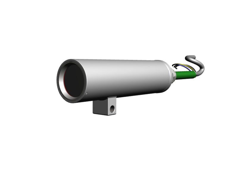
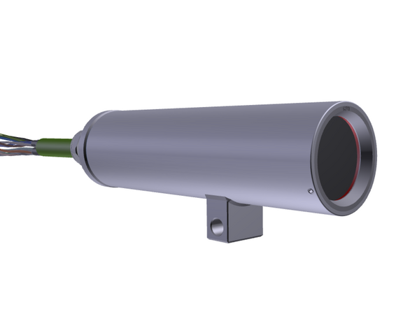
- Ultra-Compact and Leightweight Thermal Imaging Camera with integrated IR-Thermometer
- Thermal Technology with 80x80p Resolution
- Ambient Temperature range -10°C to 50°C
- Exact Temperature Measurements from -20°C to 900°C
- Thermal Sensitivity NETD 0.1°C
- Imager with Motor-Focus
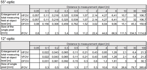
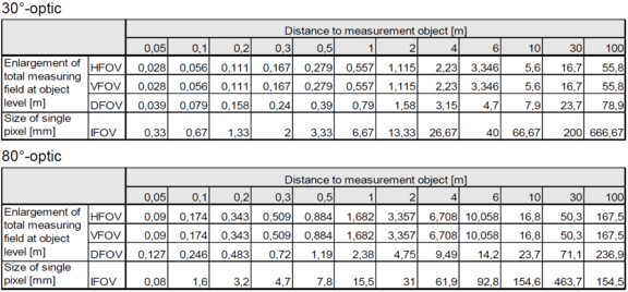
- Optical Resolution with Distance-to-Spot-Size Ratio up to 190:1
- Different Optics available (Standard, Tele, Wide)
- Autonomous Operation with Automatic Spot Finder
- Single-Cable-Solution (PoE)
- Protection Level of IP68/IP66 (IEC 60529)

First Use
All drivers are loaded automatically by the Windows operating system. No driver installation is necessary. The software starts automatically in the installed language.
- Connect the supplied USB stick to your PC.
- Start Setup.exe. Follow the wizard's instructions until the installation is complete. After installation, you will find the software on your desktop (as a program icon) and in the start menu under: Start\Programs\Optris GmbH\PIX Connect
- From the Tools → Language menu, select the language you want.
Allocating IP Adress
Note the pages 108-114 in the Software Manual
or the following Video for Software configuration
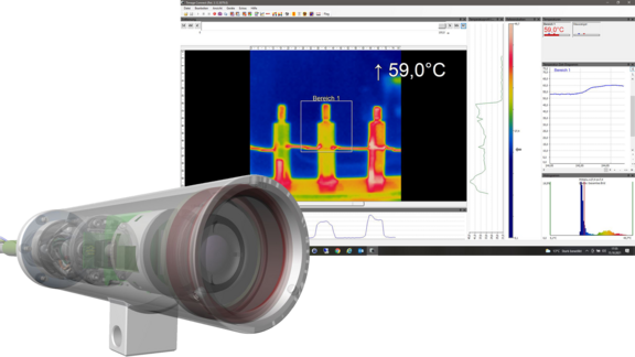
Software Basics
The configuration menu of the web surface allows an intuitive navigation and offers several configuration possibilities. For detailed documentation and information how to use the web interface, please see the optris User Manual or visit the following website
The radiometric processing of the image data enables subsequent detailed image analysis with the convenient PIX Connect software.
For this you can find variouse YouTube Tutorials of the company Optris.

Webinterface
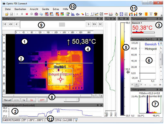
- IR-Live view from the camera
- Temperature profile: Temperature distribution on a maximum of two lines, which can be positioned anywhere in the image in terms of size and position.
- Digital display group: Possible display of all temperatures from e.g. defined measuring fields, cold spots, hot spots, temperature at the mouse pointer, the internal temperature and the chip temperature. Alarm Settings: Bar with graphical representation of a defined lower temperature threshold (blue arrow) and an upper threshold (red arrow). The color of the digits of the displayed temperature changes to RED when the upper alarm value is exceeded and to BLUE when it falls below.
- Temperature of measure area: Analyses the temperature according to the selected shape of the field, e.g. the mean value of the rectangle. This value is also shown in the live image (top right) and in the digital display.
- Reference bar: Shows a color scale with the corresponding temperature values.
- Temperature-time diagram: Shows the temperature curve over time for the selected ROI (region of interest).
- Histogram: Statistical distribution of individual temperature values in the image.
- Automatic / manual scaling of the reference bar and thus the displayed temperature range: Man., </> (min, max), 1 σ: 1 sigma, 3 σ: 3 sigma, OPT: Optimized palette
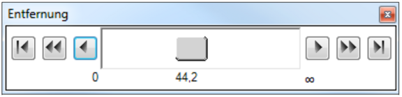
- Distance Function: Adjusting the motor focus to focus the image
- Menu and toolbar (icons)
- Symbol for switching the individual palette views in the reference bar.
- Status bar: Serial number, optics, temperature range, mouse cursor position, device frame rate/display frame rate, emissivity, ambient temperature, flag status
Cleaning
- Dirt on the viewing window must be removed as it can falsify the result of the temperature measurement.
- Never use cleaning agents containing solvents!
- Loose particles can be blown away with clean compressed air.
- Clean sight glass with soft, damp microfibre cloth (water or lens cleaner, e.g. Purosol or B+W Lens Cleaner).


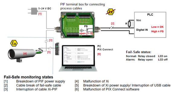
Indusrial Process-Interface (PIF)
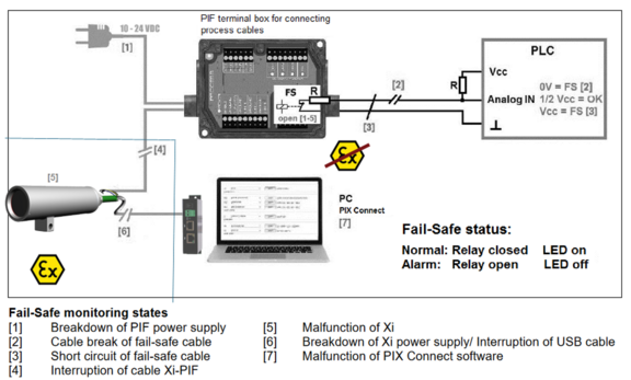
An industrial process interface with 500 VACeff insulation voltage between ExCam XI and process is available for permanent monitoring of hardware and software during operation. The PIF is equipped with self-monitoring (fail-safe mode) so that states such as interruptions in the cable connection, termination of the software, etc. can be recorded and output as an alarm. The fail-safe time constant is 1.5 seconds. The PIF is not explosion-proof and may therefore only be used in safe areas.
Process-Interface of the camera
The ExCam XI80/410 offers the following direct In- and Outputs:
Name | Description | Max. range / status |
AI or DI | Analog input | 0 - 10 V1) |
Digital input (Low-aktive = 0 … 0.6 V) | 24 V | |
AO | Analog output Alarm output | 0/4 – 20 mA 0/4 – 20 mA |
1) the AI is designes for max. 24 V, voltage level above 10 V is not interpreted
In addition the above direct in- and outputs the ExCam XI80/410 has a RS485- interface. This interface can be used to control the external, industrial PIF. When using the RS485 interfacethe direct out- and inputs are not available.
If the process interface of the camera is directly connected to external hardware (without using the supplied PIF cable) an activation of the field „Support proprietary PIF cable“ in the menu Tools/ Configuration/ Device (PIF) in the PIX Connect Software is necessary.Consider that the input of the PIF is not protected if there is a direct PIF connection! A voltage > 3 V on the INT-pin will destroy the device!
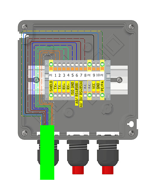
Pin assignment Industrial Process-Interface (PIF)

Programmable functions PIF
| Analog Input (AI) | Emissivity, ambient temperature, reference temperature, uncommitted value, flag control, triggered recording, triggered snapshots, triggered line-scanner, triggered event grabber, reset peak-/valley-hold, switch temperature range |
| Analog Output (AO) | Main measure area, measure area, internal temperature, flag status, recording status, line scan status, alarm, frame sync, fail-safe, external communication, autonomous status |
| Digital Output (DO) | Flag status, recording status, line scan status, alarm, frame sync, fail-safe, external communication, autonomous status |
In- and outputs
Name | Description | Max. range1) / status |
INPUT 1/2/3 | Analog- or digital input | 0 - 10 V2) |
AO 1/2/3 | Analog output 1, 2 and 3 Alarm output 1,2 and 3 | 0 - 10 V 0/4 - 20 mA |
DO 1/2/3 | Relay output 1,2 and 3 Alarm output | open/ closed (red LED on)/ 0...30 V, 400 mA 0/4 - 20 mA |
FS | Fail-Safe-Relay | open/ closed (green LED on)/ 0...30 V, 400 mA |
1) depending on supply voltage; for 0-10 V on the AO the PIF has to be powered with min. 12V.
2) the AI is designed for max. 24 V, the voltage level above 10 V is not interpreted
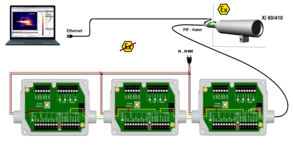
Extension up to 9 outputs
The industrial PIF has a maximum of 3 analog outputs. To use up to 9 analog or alarm outputs maximum 3 PIFs can be connected. Each stackable industrial PIF must have its own RS485 address. The address must be set directly on the board. For the PIF which is the furthest away the 120R switch (TERM. –Termination) has to be set.
Questions about our products
If you have any questions about our products please contact our Sales Team.